
Section demonstrating the standard depiction for ribs on an object.

This section demonstrates the standard of rotating holes to improve viewability.

Section of clip - many begining drafters make the mistake of hatching the left end of the section, not realizing it is an open area on this particular object.

Simple view of angled face to depict actual size

This auxiliary view depicts the true size of the angled and 'U' cut end.

This auxiliary view depicts the true size of the angled and 'T' shaped cut end.

This drawing depicts a more complicated object to demonstrate how auxiliary view aid in the visualization of the true size and shape of a side not directly facing one of the standard orthographic views.

This style of dimensioning is most common in mechanical drafting.

This style of dimensioning is most common in architectural drafting.

This style of dimensioning can be useful in moderm machine shops where coordinates can be typed into the device.

This style of dimensioning is similar to the Tabular Dimensioning, with the coordinate type annotations with the object instead of on a reference table. This style is also suitable for moderm machine shops where coordinates can be typed into the device.

Example of engineering graphics dimensioning.

Example of engineering graphics dimensioning.

Example of engineering graphics dimensioning.

Example of engineering graphics dimensioning.

Example of engineering graphics dimensioning.

Example of engineering graphics dimensioning.
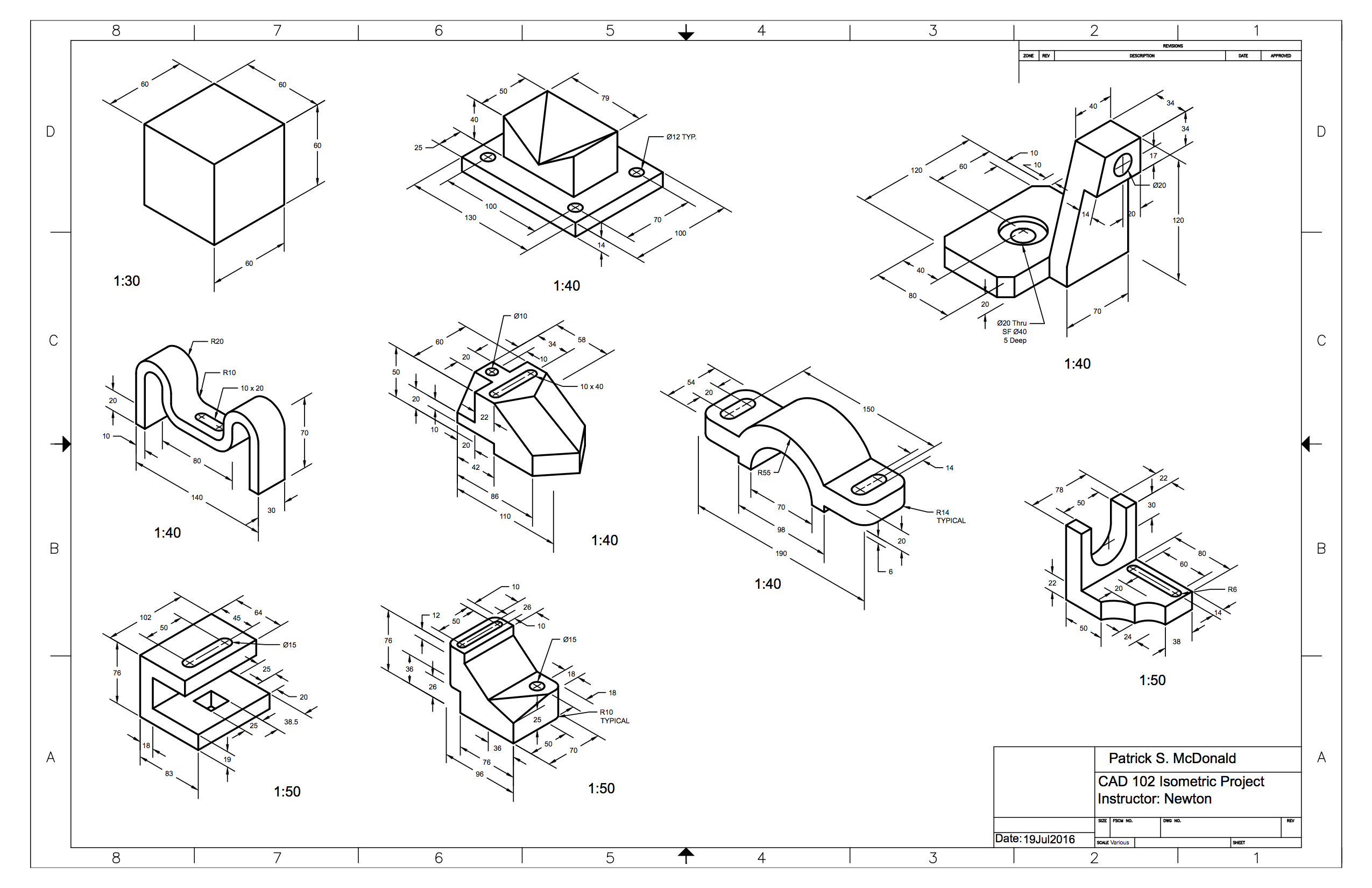
Series of mechanical objects drawn isometrically. This particular assignment was done before the lessons on mechanical dimensioning

This drawing provides examples of all the standard types of thread representations.

This drawing provides an example of a standard compression spring.

This drawing provides an example of a standard flat spring.

This drawing shows the end product of a true length calculation.

This drawing shows the end product of a true length calculation.

This drawing demonstrates parallel line development that can be used to fabricate a cutout which is formed into the 3D object.

This drawing demonstrates the more difficult triangulation development. The product is open at either end as it is a ducting transition.

This drawing provides the information necessary to cut a small scale out of the indicated material using an Epilog laser on the listed settings.

This drawing provided the information necessary to cut the cover for the paper portfolio that accompanies this web portfolio.

This depicts basic architectural drawing and dimensioning as well as simple details.
This depicts basic blocks and tables in an achitectural format.

This depicts a slightly more complicated architectural drawing that involves importing details created by someone else.

This depicts an interior furniture layout using previously defined blocks for both the floorplan and the chart.

This depicts a very simple house design done in AutoCAD 3D. It features multiple features and fixtures created for the drawing, as well as ones imported from actual manufacturers' web sites.

This depicts the same house as the previous image, with surfaces applied.

This the kitchen from the 3D house as seen from a placed camera and rendered for a more realistic looking image.

This depicts an oil sink drawn using AutoCAD 3D.

This depicts the orthographic views developed using the AutoCAD 3D oil sink model.

This depicts the section views developed using the AutoCAD 3D oil sink model.
Additional AutoCAD Models and Drawings
This depicts the final project from a Custom CAD course. The objects are almost entirely made up of anotative blocks with multiple visibility states. The parts table is made up of real manufacturer parts that could be ordered to create the bar.

Sheet 2.

Sheet 3.

Sheet 4.

Sheet 5.

Sheet 6.

Sheet 7.

This depicts one of the more involved objects created SOLIDWORKS.

This depicts a block drawn using SOLIDWORKS.

This depicts the orthographic drawings produced in SOLIDWORKS from the previous model. The student version of the software appears to chop off either end of the 11x17 page.

This depicts a keyed shaft drawn using SOLIDWORKS. The planes were left visible to provide a little insight on how the model was developed

This depicts the orthographic drawings produced in SOLIDWORKS from the previous model. The student version of the software appears to chop off either end of the 11x17 page.

This depicts a V block assembly formed from independent parts created and assembled in SOLIDWORKS.

This depicts an assembly in SOLIDWORKS formed from provided components.

This depicts an object using both revolve and sweep features in SOLIDWORKS.
Additional SOLIDWORKS Models and Drawings


This code will create a multiplication table, and then surround it with a box. This problem was done to demonstrate nested looping in AutoLISP.


This code will create block of a desk, ask the user a series of questions on details of a desk array, and then draw the array of desks where indicated. This was done as a group project, for which I was team lead. Some of the code is not exactly the way I would have done it myself, but it works - and part of being a team lead is accepting what is good enough so that deadlines can be met.


Part of the requirement for the final project was to read required information from a file - we decided to have the available colors for the desks come from the text file. We also added the DCL so we could get the colors to show in a pull down menu with one additional option - rbdesk - which stands for rainbow desk. This last option was the difficult part, as we had to create layers for all the different possible colors and they cycle through them to create an array of multiple different colored desks.
Section 5: Threads and Springs
Section 8: Fabrication Projects